The Great Electronics Reorg of 2009

March 30 - April 18, 2009

Decided all the electronics should live in the house, not in the garage.

First step -- Rearrange bedroom to accommodate giant cabinet of electronics.


  • First, took everything out of bedroom -- bed, desk, mattress, ...
  • I split the desk apart and changed from "L" shape to straight shape after moving bed and desk to at least four configurations in a frenzy of "physical engineering". My usual is careful measurements and graph paper, or once I even tried Sketchup.
  • Installed pegboard thingy.
  • Installed curtain rods and hung up curtains.
  • Installed a new phone jack. I broke the original by dropping a big piece of plywood on it.
  • Installed new DSL modem which I got some months ago.
  • Fixed my wireless connection, which hasn't functioned for oh so long.
  • Installed and wired all the routers and cables and junk into the desk and tidied it all up.
  • Moved two file cabinets into place.
One weekend day spent beefing up the cabinet because all the shelves were bowing in the middle. So out came the saw, drill, wood, etc and I made "cleats".


Cleat with crossbars installed in cabinet.


Moved cabinet from garage to apartment with the help of my neighbor. Then actually gathered all the electronics from everywhere and sorted them in the cabinet (somewhat). Also I cleaned the garage while I was at it and got rid of some stuff including a cart that was really in the way. It's great now, I can work in there again. Before, I couldn't get to the workbench. Plus, removing the cabinet means finally a place to put the bandsaw.

The cabinet all put back together.


Contents of cabinet

Miracle Machine

The CNC mill that makes it all possible. Thanks, Steamer!!!


Robot Shoulder Bracket Rev 2.0 - Morning

Saturday 28 March 2009

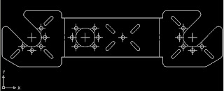
Drew up modified bracket with slots.

Robot On...

Friday night was spent measuring brackets and servos to recalculate the diameter of the big holes so the servo horns will fit through the holes. Oh, the first bracket I made doesn't fit on the servos. Screw holes are way to small and the big holes are a tiny smidgen too small to clear. The servos and brackets shown are from my Kondo KHR-1.


Another problem, bracket really need slots instead of holes but QUITE reluctant to make the change because it will destroy that nice bracket :( Boo hoo hoo.

LEGO Mindstorms

Friday March 27 2009 - Day

Worked on LEGO robot for Pit of Despair contest. Jeronimo made robot that crosses the Pit. Yay! Takes about 1 minute to get 2/3 of the way, maybe 2 minutes to cross? Then decided to add another motor, which I think will work, we didn't quite finish, so right now still about 50/50. It sometimes does a front flip going into the Pit and lands on its head.

Makin' Like Krazee at Work

Monday March 23 - Thursday March 26
Crazy busy at work preparing many projects and robots for a show and a photo shoot

Monday
Vibrobots at work

Tuesday
Vibrobots
Wired motor board into VCR, heisted two switches on VCR to control the circuitry
Changed to 7.2V R/C car battery (bought it, charging)

Wednesday
Installed battery, jamming, mechanical bits for VCR, motor toast
Finally bought new motor kit, made it, it works
End of the deadline for show, krazee time! Fun tho.

Thursday
Soldered last four LEDs for Peggy
End of deadline for photo shoot, gathered all projects
Bent some wire with new bendy tool

Elephant Gets Simpler

Wednesday 25 March 2009

Toolpaths are too tight for 1/8" bit to negotiate, changed to simpler design with only three parts.

Elephant Puzzle

Monday 23 March 2009

Started drawing custom puzzle to cut out on CNC. It's a Heffalump!

Soldering 500 LEDs

Saturday through Monday, 23 March 2009

Soldered up a "Peggy", which is sort of a programmable LED light bright, for work. It probably had between 400 and 500 LEDs on it.

Old School Relay Motor Driver

Sun 21 March 2009

I dug out this schematic of the very first robot I ever made, which used relays to drive the motors. Think that is part of the reason I used the relay in the previous post -- so I could understand how the transistor turns them on and off. I have felt puzzled for years after building that gosh darn robot. Now I can see why -- the schematic is like spaghetti -- I can give my ' inner sixteen year old' electronics newbie a break. Apparently the -6/+6 gives directional control via the relay, pretty clever, eh?

That's all hand-drawn, serious geek points.

The Fabricated PCB

Sat 21 March 2009

Check it out, the actual PCB is back from the fab house.

Motor Driver Circuit

Friday-Saturday March 20-21 2009

Made a circuit to turn a motor on for a short time when a button is pressed. We had a bunch of 3904s lying around and no power transistors, but we had a bunch of these 5V relays, so I used a 3904 and a relay. The motor is going to be overvolted and overworked pretty hard I suspect. Fun stuff, actually had to do some calculations and look up values in data sheets to figure out the sizing of the resistors. Not that I knew how, much thanks to the internet and www.kpsec.freeuk.com.


HyperBot

Thursday March 19 2009

Made a hyperactive vibrobot at work. Shortened the legs and increased the wobble with an eccentric weighted piece. Thanks to Lindsey for the doggie parts -- googly eyes, pointy ears, tail.

Completed Puzzle

Wed March 18 2009

Cut the remaining three pieces of the puzzle. Fits like... well, like fine machinery.


Puzzle Pieces

Monday March 16 2009

The first two pieces of the puzzle.

The Bottle Opener

March 4 2006

This is my favorite of all the parts I've CNC'd for school. I call it The Happy Tool.